

Textures can be created and defined as two-dimensional images which are mapped onto a surface. Textures of a surface can be set in two different ways. A texture can be set as a viewing attribute so that all instances of a surface have the same texture (see Appendix II), or it can be set during string interpretation so that instances of a surface may have different textures. Textures can be set during string interpretation by the following module:
6.1 Textured Bicubic Surfaces
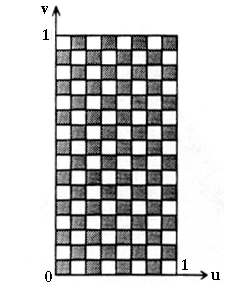
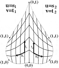
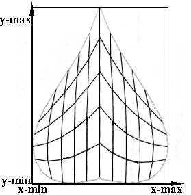
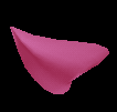
To map the texture onto the surface, there are two ways of transforming the object coordinates (x,y,z) into the texel (pixel of the texture image) coordinates (u,v)[6]:
 |
|---|
| Figure 6.1 u,v coordinate system |
 |
 |
|---|---|
| Figure 6.2 Map onto each patch |
Figure 6.3 Map onto entire surface u=(x-(x-min))/((x-max)-(x-min)) v=(y-(y-min))/((y-max)-(y-min)) |
6.2 Textured Generalized Cylinders
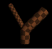
Textures on generalized cylinders can only be set during string interpretation by the module @Tx(index). The texel coordinate system is specified in the following way: the u coordinate goes around the segment circumference, where u is an element of [0,1], and the v coordinate increases along the cylindrical axis in such a way that the aspect ratio of the image pixels mapped onto the surface is always 1. The v coordinate can be computed using the following equation:
where l is the segment length, c is the circumference of the base disk, Rx and Ry are sizes of the texture image, and v0 is the final texel coordinate from the previous line segment (see Figure 6.4)[7].
v0=0 is the value of the very first line segment. The starting value for the subsequent segment is the last value of texel v.
The image is repeated along the stem and the left and right sides of the texture are aligned.
 |
|---|
u,v coordinate system |
|
Example:
The following L-System maps a texture onto a generalized cylinder.
#define STEPS 1
#define CLEN  0.35
#define NR 5
#define LEN  1
#define LENLOW 1
#define LENMID 1
#define LENUP 1
#define RIGHT 45
#define LEFT 45

Lsystem: 1
derivation length: STEPS

Axiom: \(0),(95)#(2)@Tx(1)@Gs
	F(LENLOW*2) +(LEFT) F(LENMID*2) -(RIGHT) F(LEN*3)
	F(LENUP*2)@Ge(NR)

homomorphism
F(x) --> f(x)@Gc(NR)

endlsystem
|
6.3 Textured Polygons
Textures on polygons can only be set during string interpretation by
the module @Tx(index). Polygon vertices h and
r are used to determine texture coordinates u and
v. The turtle's heading vector of the first polygon vertex
v0 is used to define the h axis
and the turtle's right vector (left vector in opposite direction)
of the first polygon vertex v0 is used to define the r axis. The h and r coordinates are scaled to the interval [0,1] to obtain the u and v texture coordinates (see Figure 6.5)[8].
 |
|---|
| Figure 6.5 Map onto entire surface u=(r-(r-min))/((r-max)-(r-min)) v=(h-(h-min))/((h-max)-(h-min)) |
|
Example:
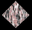
The following example maps a texture onto a polygon.
#define STEPS 1
#define INDEX 1

Lsystem: 0
derivation length: STEPS

Axiom: @Tx(INDEX){.-(45)F(4).+(90)F(4).+(90)F(4).+(90)F(4).}

endlsystem
|
 |
 |
 |
 |
 |
Preface Parameters Appendix I Appendix II References |
|---|---|---|---|---|---|
| Index | Circles and Spheres | Generalized Cylinders | Surfaces | Textures |