5.1 Predefined Surface Models
The following module represents a predefined surface:
|
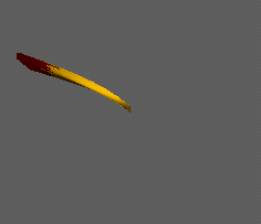
Example:
The following example uses three predefined surfaces to model the petal of a flower.
#define SIZE 1500
#define CURVING 0
#define SPREAD 30
#define SEEDS 0
#define RAYS 89
#define CON SEEDS+RAYS
#define CURVV 90/(CON)*CURVING
#define PETALS 55
#define PETANG 121
#define DROOPING 0.14
#define DROP PETANG/PETALS*DROOPING
#define PETSIZE 1.5
#define SIZEINC 0.000
#define ADJ 90*CURVING
Lsystem: 1
derivation length: SEEDS+RAYS+PETALS+1
ignore: z
Axiom: /(180)f(SIZE+SIZE)-(90)f(SIZE+SIZE)-(90)f(SIZE)-(90)f(SIZE)/(60);
(1)A(0)
* < A(n) > * : * --> A(n+1)D[+(n*137.5)^(n*CURVV)f(SPREAD*n^0.5)C(n)]
* < C(n) > * : (n
|
5.2 Developemental Surface Models
L-System modules allow the user to produce polygons and surfaces from scratch. The following modules define the boundaries and vertices of polygons:
} terminates, draws, and fills the current polygon.
. specifies a vertex at the current position of the turtle.
Note that it is essential to understand that the polygon stack and the branching stack may not be interchanged. These are two separate stacks completely independent of each other.
|
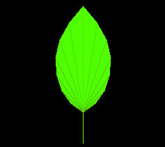
Example:
The following example specifies a surface using a branching structure.
#define STEPS 15

Lsystem: 0
derivation length: STEPS
Axiom: G(2)[A][B][a][b]

A --> [+A{.].C.}
B --> [-B{.].C.}
a --> ;;;[+a.].C.
b --> ;;;[-b.].C.
C --> ;G,C

endlsystem
|
5.3 Developmental Bicubic Surfaces
The following modules can be used to specify Bezier form bicubic surfaces:
@PC(i,r,c) assigns the control point of surface i in row r and column c to the current position of the turtle.
@PD(i,s,t) draws the surface defined by the control points of surface i using s lines along the rows and t lines along the columns.
|
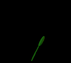
Example:
The following example specifies a bicubic surface.
#define PSTEPS 200
#define RIBPIT1_3 121
#define RIBPIT2_3 101
#define RA1_3 RIBPIT1_3-180
#define RA2_3 RIBPIT2_3-180
#define RIBLEN0_3 2
#define RIBLEN1_3 2
#define RIBLEN2_3 2.1
#define CROSS0_3 0.1
#define CROSS1_3 2
#define CROSS2_3 2.5
#define CROSS3_3 0.1
#define SEG00_3 0.1
#define SEG01_3 2.6
#define SEG10_3 4
#define SEG11_3 0.1
#define CROSSPIT0_3 129
#define CROSSPIT1_3 39
#define CROSSPIT2_3 129
#define CROSSPIT3_3 200
#define SEGPIT0_3 180
#define SEGPIT1_3 180
#define CP0_3 CROSSPIT0_3-180
#define CP1_3 CROSSPIT1_3-180
#define CP2_3 CROSSPIT2_3-180
#define CP3_3 CROSSPIT3_3-180
#define SP0_3 SEGPIT0_3-180
#define SP1_3 SEGPIT1_3-180
#define CROSSTRN0_3 186
#define CROSSTRN1_3 166
#define CROSSTRN2_3 163
#define CROSSTRN3_3 180
#define SEGTRN0_3 135
#define SEGTRN1_3 335
#define CT0_3 CROSSTRN0_3-180
#define CT1_3 CROSSTRN1_3-180
#define CT2_3 CROSSTRN2_3-180
#define CT3_3 CROSSTRN3_3-180
#define ST0_3 SEGTRN0_3-180
#define ST1_3 SEGTRN1_3-180
#define DOTS_3 1
#define Pr 0.01
#define PFN(t,L,D)(3*(L)/(D)^2*(t)^2-2*(L)/(D)^3*(t)^3)
#define PLR 0.0
#define PWR 0.55
#define PSR 0.55
#define PPAR 0.55
#define PRAR 0.55
#define PTAR 0.1
#define PRAD 0.2

lsystem: 3
derivation length: PSTEPS

axiom: p

p --> UVWXYZ

U --> @PS(0)[+(0,0,90,90+CT0_3,0,PTAR)&(0,0,0,CP0_3,PRAD,PPAR)
	f(0,0,0,CROSS0_3,PRAD,PWR)@PC(0,0,0)[+(0,0,0-45,ST0_3,0,PTAR)
	&(0,0,0,SP0_3,PRAD,PPAR)f(0,0,0,SEG01_3,PRAD,PSR)@PC(0,1,0)]
	-(0,0,0-135,180-ST0_3,0,PTAR)^(0,0,0,SP0_3,PRAD,PPAR)
	f(0,0,0,SEG00_3,PRAD,PSR)@PC(0,0,1)]

V --> [-(0,0,90,90+CT0_3,0,PTAR)&(0,0,0,CP0_3,PRAD,PPAR)
	f(0,0,0,CROSS0_3,PRAD,PWR)@PC(0,0,3)[-(0,0,0-45,ST0_3,0,PTAR)
	&(0,0,0,SP0_3,PRAD,PPAR)f(0,0,0,SEG01_3,PRAD,PSR)@PC(0,1,3)]
	+(0,0,0-135,180-ST0_3,0,PTAR)^(0,0,0,SP0_3,PRAD,PPAR)
	f(0,0,0,SEG00_3,PRAD,PSR)@PC(0,0,2)]

W --> f(0,0,0,RIBLEN0_3,0,PLR)[+(0,0,90,90+CT1_3,0,PTAR)
	&(0,0,0,CP1_3,PRAD,PPAR)f(0,0,0,CROSS1_3,PRAD,PWR)@PC(0,1,1)]
	[-(0,0,90,90+CT1_3,0,PTAR)&(0,0,0,CP1_3,PRAD,PPAR)
	f(0,0,0,CROSS1_3,PRAD,PWR)@PC(0,1,2)]

X --> &(0,0,0,RA1_3,PRAD,PRAR)f(0,0,0,RIBLEN1_3,0,PLR)
	[+(0,0,90,90+CT2_3,0,PTAR)&(0,0,0,CP2_3,PRAD,PPAR)
	f(0,0,0,CROSS2_3,PRAD,PWR)@PC(0,2,1)][-(0,0,90,90+CT2_3,0,PTAR)
	&(0,0,0,CP2_3,PRAD,PPAR)f(0,0,0,CROSS2_3,PRAD,PWR)@PC(0,2,2)]
	&(0,0,0,RA2_3,PRAD,PRAR)f(0,0,0,RIBLEN2_3,0,PLR)

Y --> [+(0,0,90,90+CT3_3,0,PTAR)&(0,0,0,CP3_3,PRAD,PPAR)
	f(0,0,0,CROSS3_3,PRAD,PWR)@PC(0,3,0)[+(0,0,0-135,ST1_3,0,PTAR)
	&(0,0,0,SP1_3,PRAD,PPAR)f(0,0,0,SEG11_3,PRAD,PSR)@PC(0,3,1)]
	-(0,0,0-45,180-ST1_3,0,PTAR)^(0,0,0,SP1_3,PRAD,PPAR)
	f(0,0,0,SEG10_3,PRAD,PSR)@PC(0,2,0)]

Z --> [-(0,0,90,90+CT3_3,0,PTAR)&(0,0,0,CP3_3,PRAD,PPAR)
	f(0,0,0,CROSS3_3,PRAD,PWR)@PC(0,3,3)[-(0,0,0-135,ST1_3,0,PTAR)
	&(0,0,0,SP1_3,PRAD,PPAR)f(0,0,0,SEG11_3,PRAD,PSR)@PC(0,3,2)]
	+(0,0,0-45,180-ST1_3,0,PTAR)^(0,0,0,SP1_3,PRAD,PPAR)
	f(0,0,0,SEG10_3,PRAD,PSR)@PC(0,2,3)];(255)@PD(0,8,8)

endlsystem
|
 |
 |
 |
 |
 |
Preface Parameters Appendix I Appendix II References |
|---|---|---|---|---|---|
| Index | Circles and Spheres | Generalized Cylinders | Surfaces | Textures |